Engineering portfolio
Austin Zhai
Computer Engineering · University of British Columbia
Experience
Advanced UAV Tech
Two things came out of this internship. I designed a flight controller board from scratch, aimed at the company's move into recreational drones, and that is the first thing below. The rest of the summer went on a drone that checks warehouse pallets for damage at DHL sites, where I led a team of 5. A pilot flies it down an aisle filming the shelves, and software the team trained reads that footage back and marks which pallets are damaged. My side of that was the electronics: I sized and built the power system, wired the whole stack onto a 20 inch carbon fiber frame, tuned it until it could hold still indoors where there is no GPS to lock onto, and designed and printed landing legs when nothing off the shelf fit our motors. I also ran the project day to day and was the point of contact at DHL.
Start here · Designing a flight controller from scratch
This is the piece of work I am proudest of. The company has always been a contract shop, and leadership wanted a second line of business that did not depend on winning contracts: recreational drones, sold off a shelf.
- On a product made by the thousand, every dollar in the parts bill multiplies, and the flight controller is one of the priciest parts in a small drone
- A board you buy is built to suit everybody, with extra sensors, ports and features most pilots never use. A weekend hobby pilot pays for all of it anyway
- Mine carries only what the job needs: a processor, one motion sensor, a regulator, a USB port, and connections for the motors, receiver and battery
- Fewer parts means a smaller, cheaper board, and owning the design means the company is not tied to a supplier’s stock or roadmap
- Runs off USB at a desk or off the battery in the air, with a pair of diodes so the two supplies can never push current into each other
- The reference design used a motion sensor that has since been discontinued, so I moved to a current part that is also cheaper and smaller
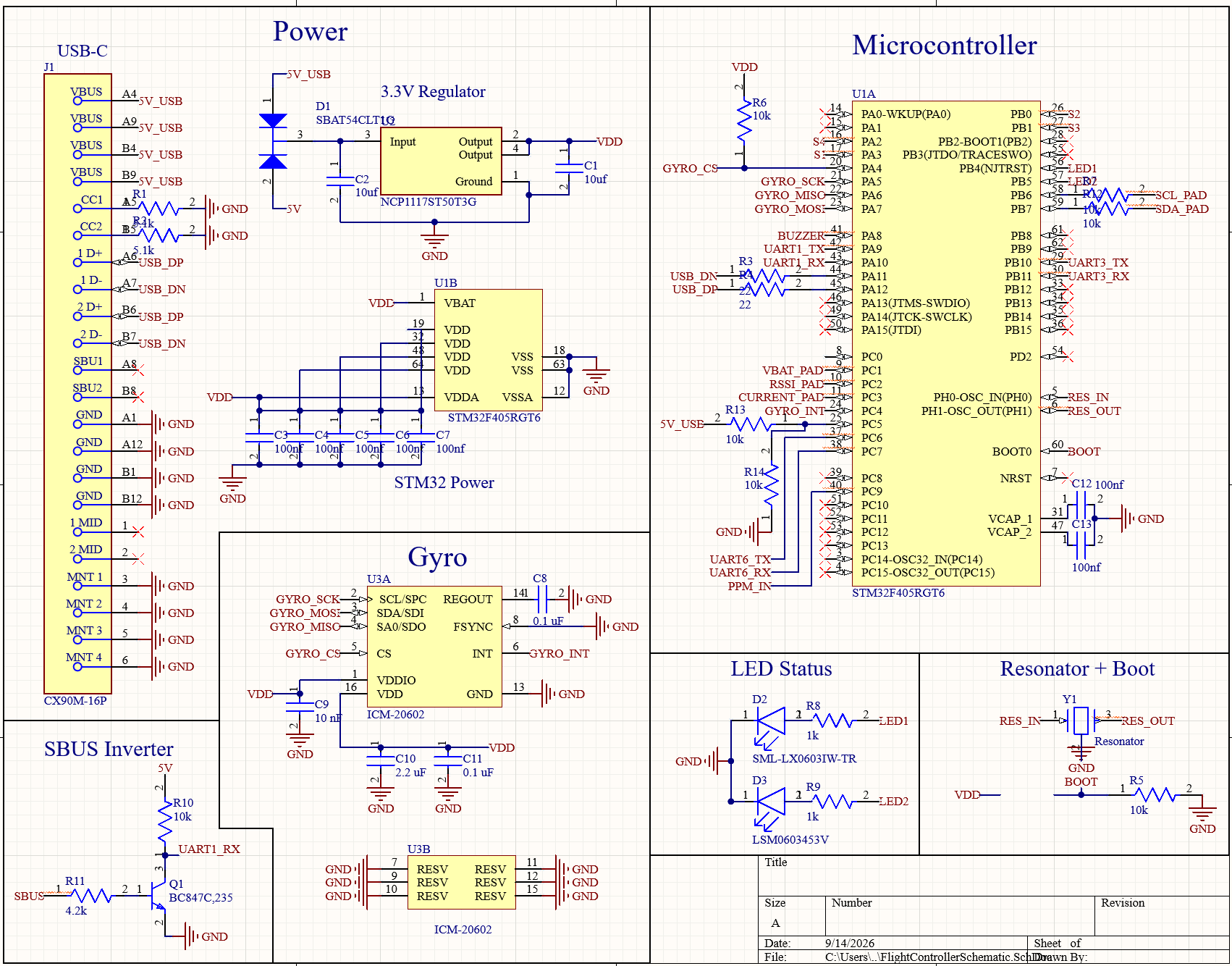
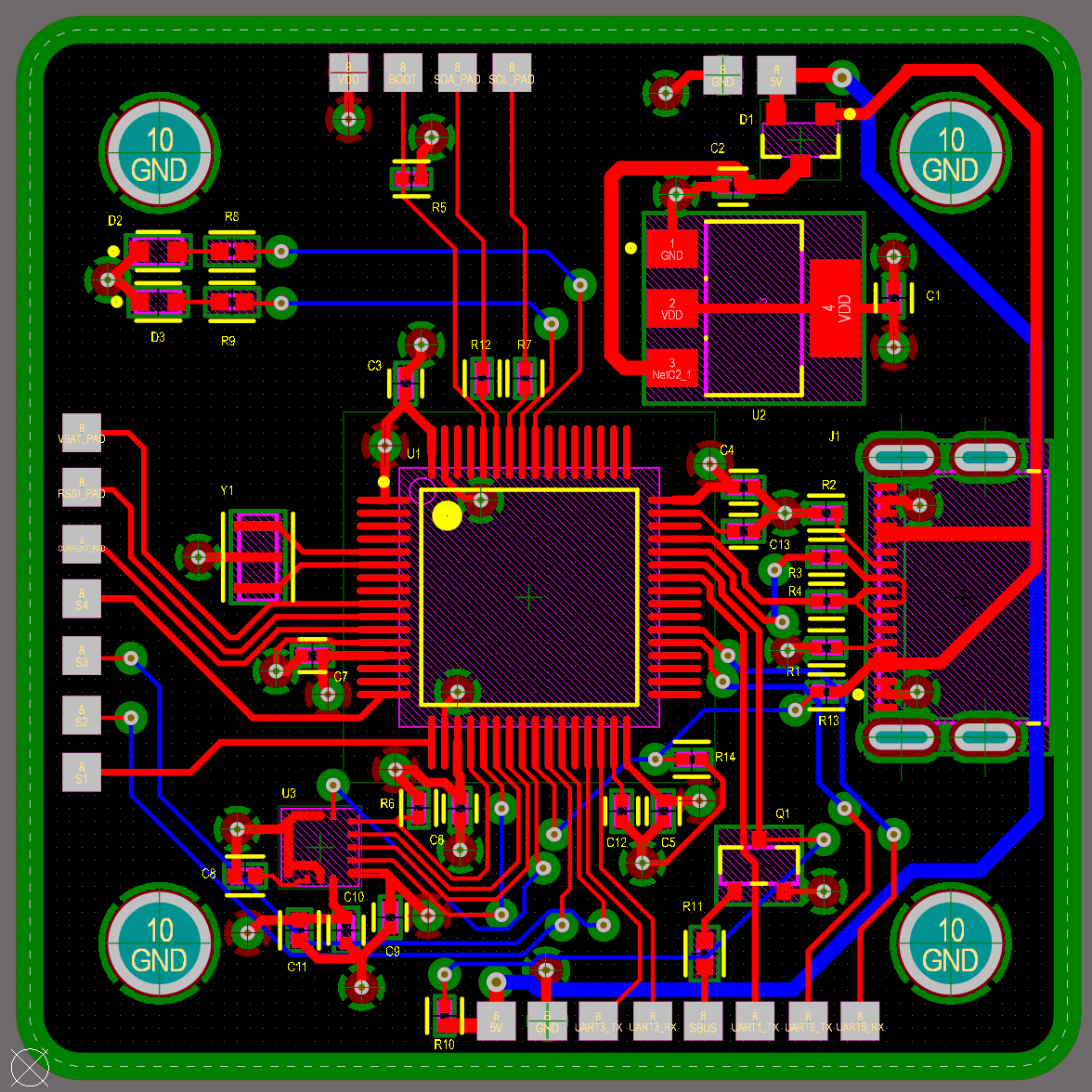
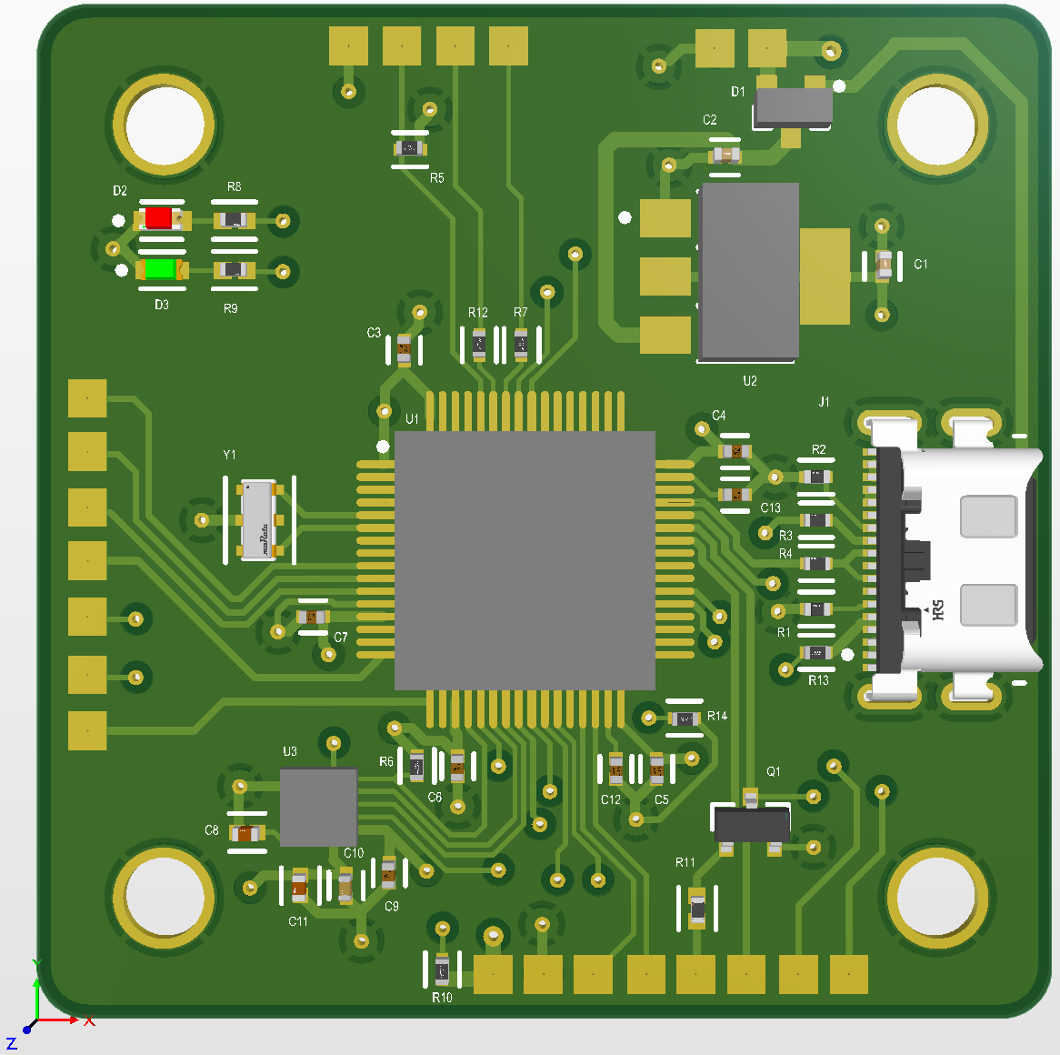
Where that board actually stands
It is not built. The design finished at the end of my internship, so right now it is a schematic and a board layout, with the full-time electrical engineers reviewing it. I expect that review to find things: it was the most complex board I had drawn, and some faults only show up on real hardware.
- Next: engineering review and corrections, then a small prototype run
- Then bench testing, because a board that looks right and a board that flies are not the same claim
- Then firmware, its own job: a blank processor does nothing until every pin is mapped to the motor, sensor or radio it connects to
- What it already settled: what a stripped-down in-house board looks like, and what it costs against buying one in
The problem
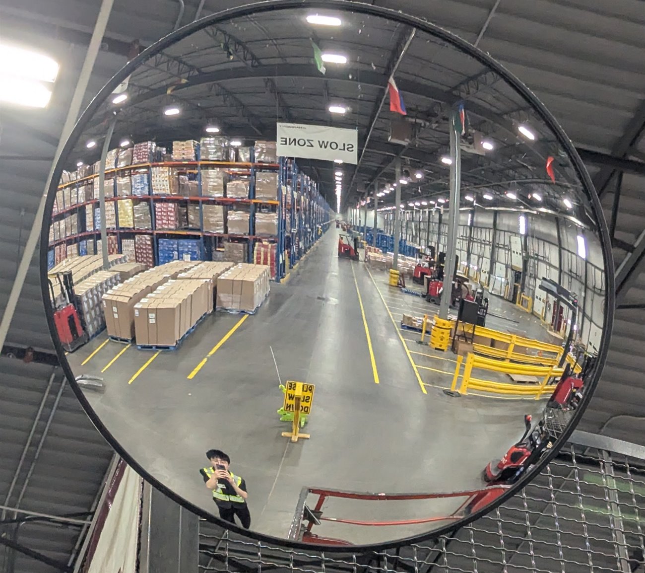
Everything from here down is the project I spent most of the summer on. Warehouses check pallets for damage by eye, one at a time, and a large DHL site holds thousands of them. We wanted to fly an aisle once and let software do the looking. I ran the meetings with DHL, so what they needed came back to the team through me.
- Damage gets spotted by whoever happens to walk past it
- Pallets are stacked well above head height, so the top rows are the hardest to check
- A drone can film a whole aisle, top shelf included, in a single pass
Prototype
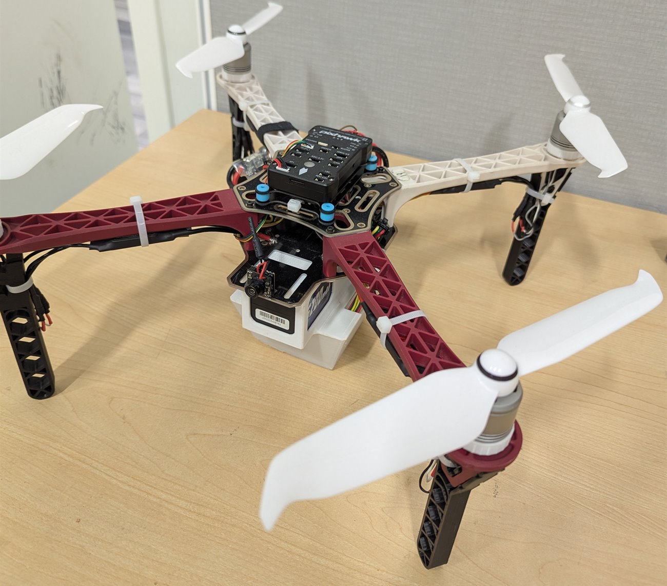
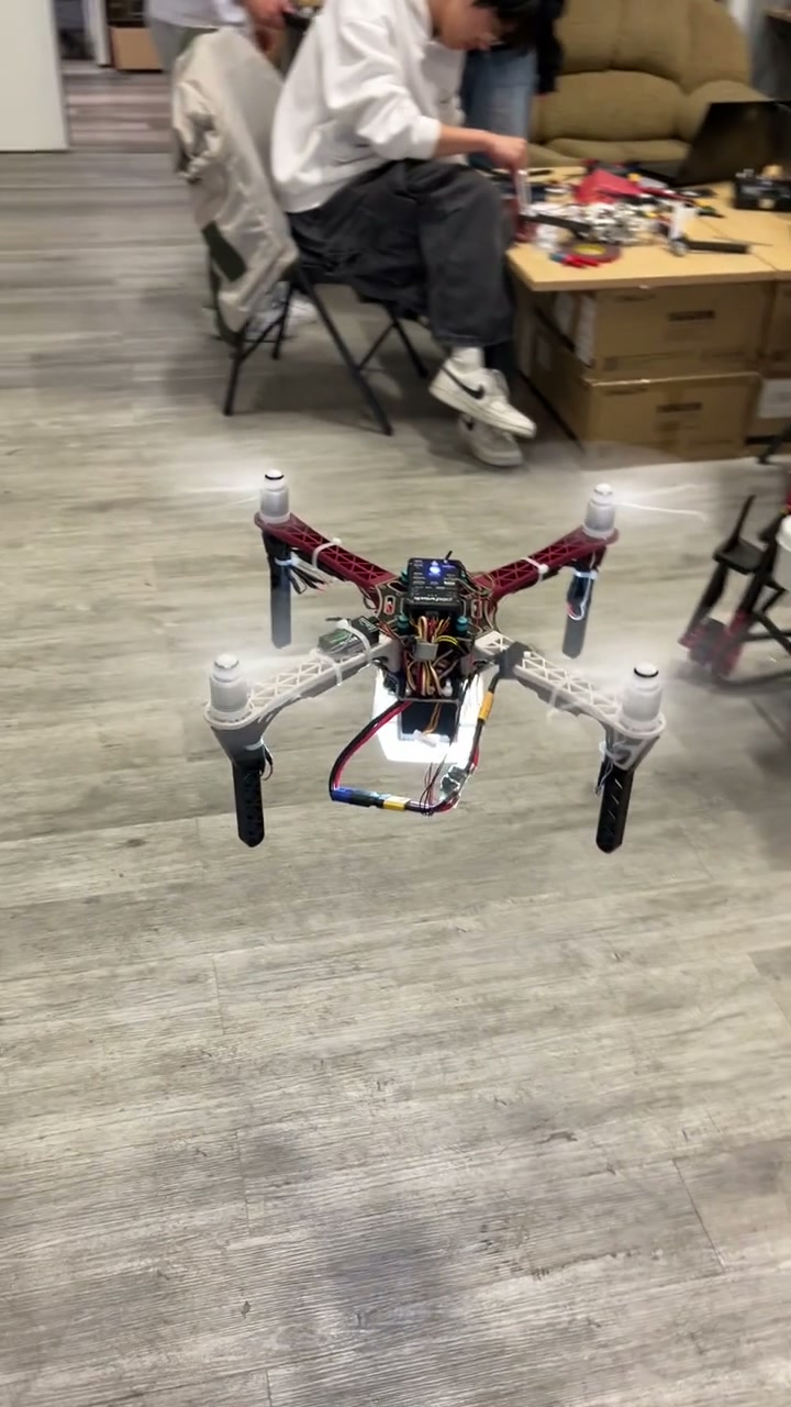
We started with a drone the company already owned, one of its light-show quads. It was never going to be the final build. It was there to answer a single question.
- The question: how does a drone hold still indoors, where there is no GPS to lock onto?
- The answer: an optical flow sensor, a small downward camera and laser rangefinder that watches the floor slide past and works out how far the drone has drifted
- Once it was fitted and tuned the drifting stopped, and everything after this was designed around it
Power system
How long the drone stays up decides how much of a warehouse you can cover in one go, and that comes down to the battery. So I worked the flight time out on paper before we bought anything, rather than picking a battery and hoping.
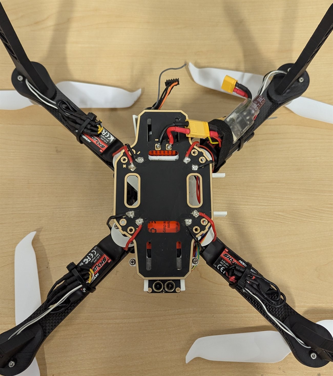
- One battery feeds all four motors, the flight controller and the camera
- Everything runs through a board I wired up that splits that single supply out to each of them
- Roughly 40 soldered connections across the whole drone, every cable cut to length and heat-shrunk
An estimate, not a measurement. The drone was never put on a scale and never flown down to empty, so treat it as the ballpark it is. The last fifth of the battery is off limits because draining a pack that far damages it.
Final airframe
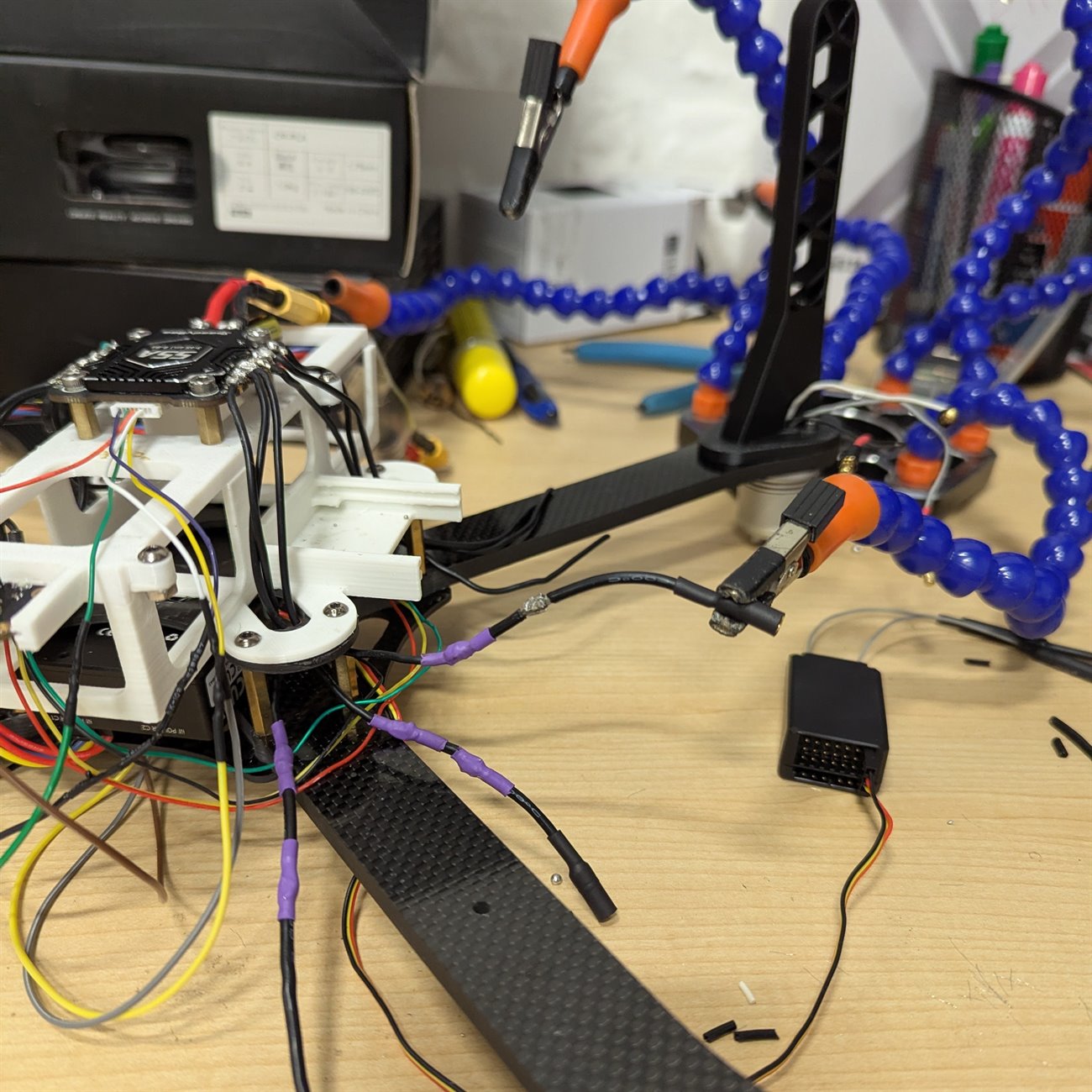
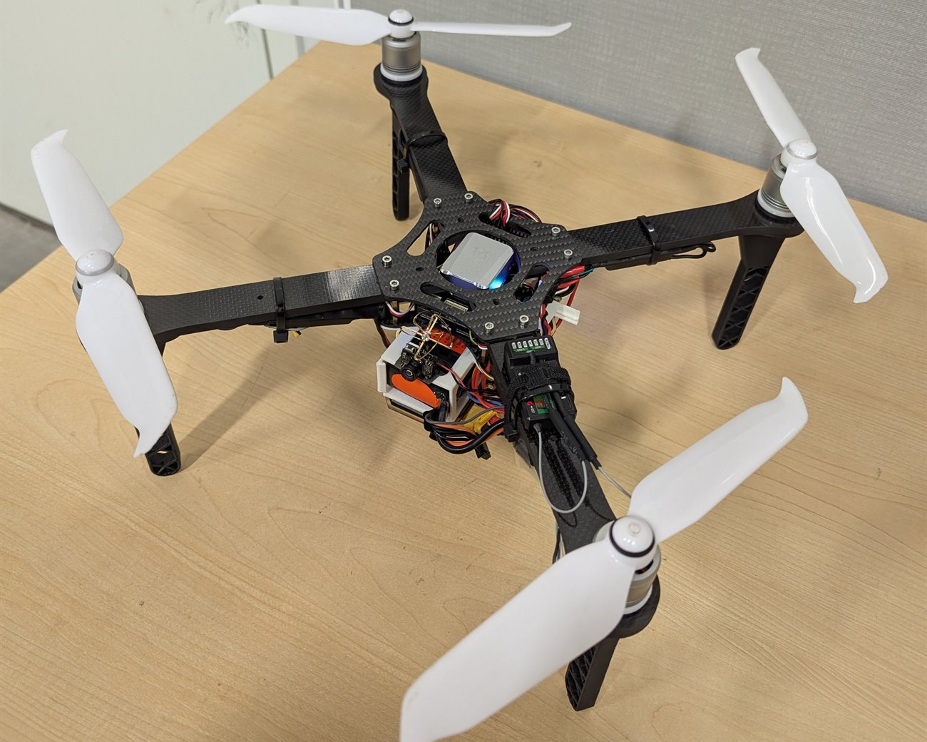
The prototype could not carry everything we needed, so we moved onto a bigger 20 inch carbon fiber frame. I assembled and wired this one myself, and designed the parts that did not exist off the shelf.
- A better flight controller than the prototype had, with the optical flow sensor mounted underneath
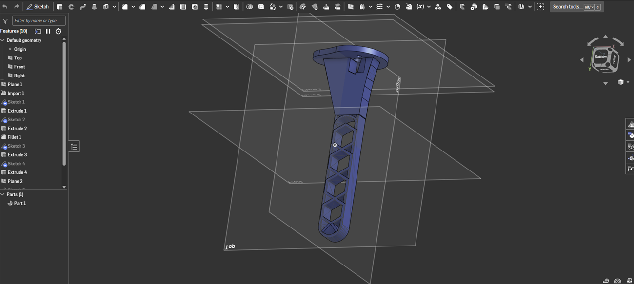
- No landing leg on the market fitted our combination of motors and frame, so I modelled our own around the real parts and printed them
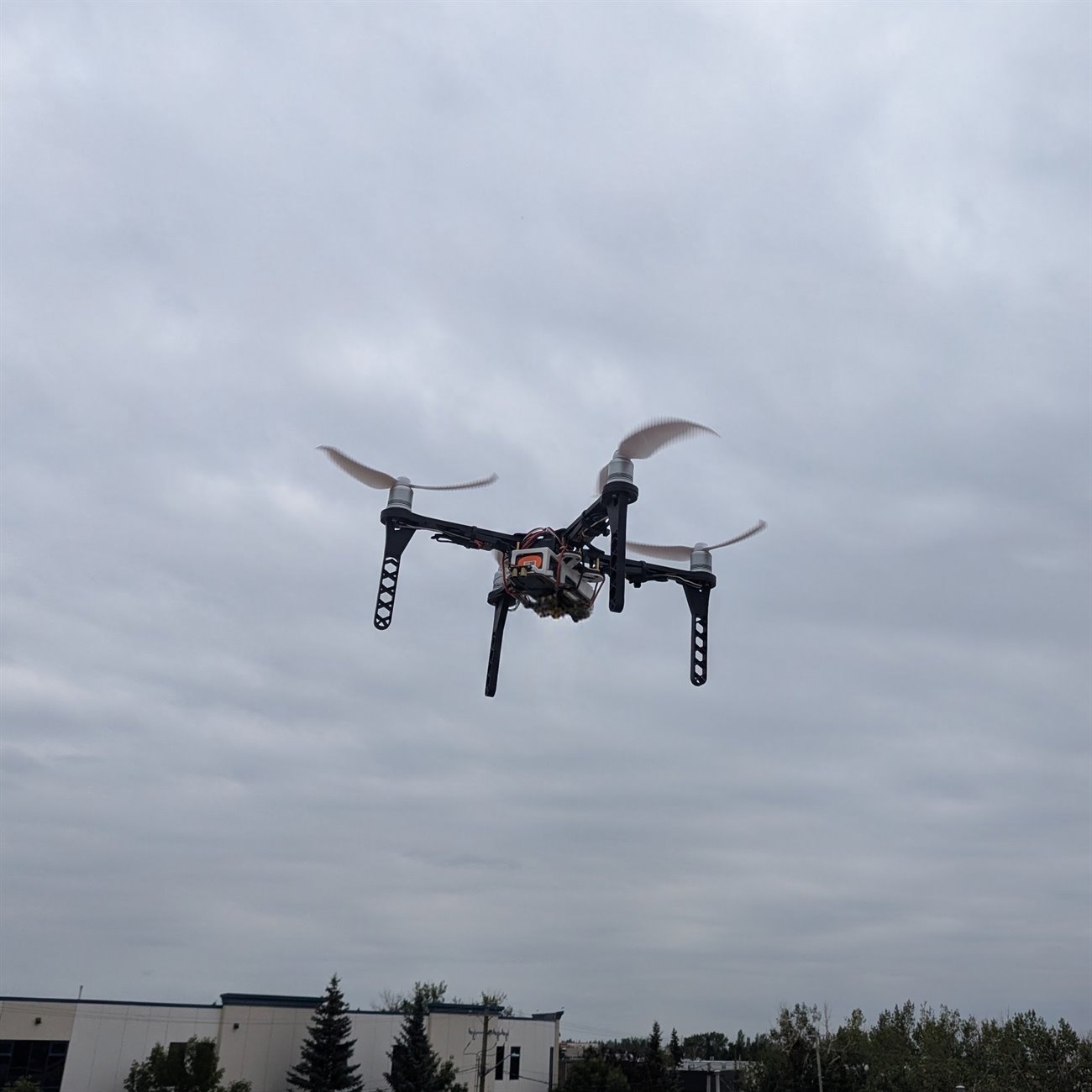
- They are hollowed out in a hex pattern to save weight without going floppy, and they are the legs holding the drone up in the photos below
- Then tuned until it held still indoors
Flying it
A pilot flew the drone down the aisle and filmed the racking. That sounds like the easy part, but it was the part everything downstream depended on.
- If the drone drifts or wobbles, the video blurs
- A blurred frame is a pallet the software cannot read
Getting the footage off the drone
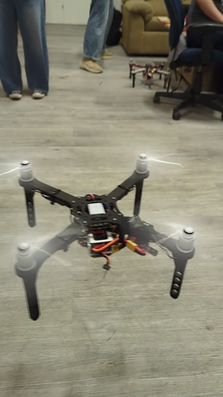
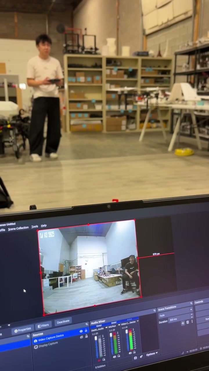
The footage came off the drone live. It carried a tiny camera and transmitter, and the picture arrived on a laptop while the drone was still in the air.
- Camera and transmitter in one part, 4.7 g and about the size of a thumbnail
- It beams to a receiver plugged into a laptop, which records the feed
- That recording is what gets fed through the software afterwards
Teaching it to recognise a damaged pallet
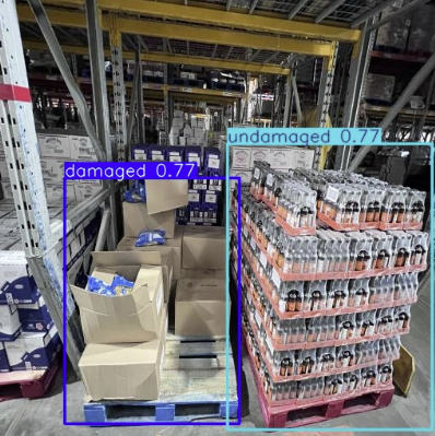
Before software can spot damage, someone has to show it thousands of examples. We labelled every training photo by hand, drawing a shape around each pallet and tagging it twice: damaged or not, and stacked flat or in a pyramid.
- Both tags sit on the same pallet, which would have the model draw two boxes around every one it finds
- So we trained it on the damage tags alone, and saved the stacking question for a later step
Training the models
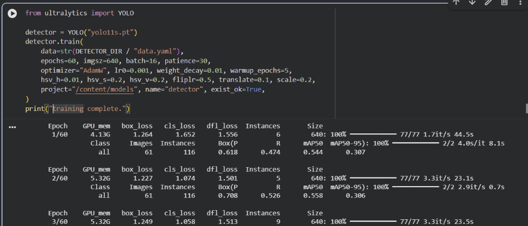
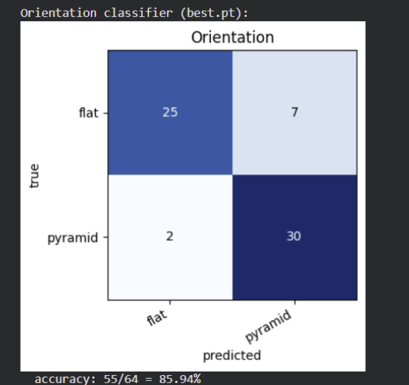
Three models chained together. The first finds the pallets, and the other two look at each pallet it found: one says whether it is damaged, the other whether it is stacked flat or in a pyramid.
- Damaged pallets are rare in the training photos, so the damage model is deliberately tuned to over-report
- Missing a broken pallet costs a lot more than sending someone to double-check a good one
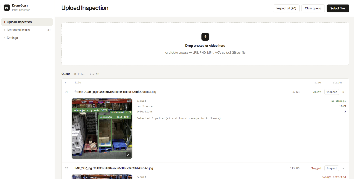
DroneScan, the app clients actually use
None of it is worth much if a warehouse manager cannot run it, so the team wrapped the whole pipeline in an app called DroneScan. You hand it the footage from a flight and it hands back a report.
- Drop in photos or a whole video, and it pulls the frames out for you
- Every pallet comes back outlined, marked damaged or clear, with a confidence score
- Filter a long list down to just the damaged ones
Galaxy Instrumentation and Controls Inc
This was my first real look inside industrial automation: the controllers, monitoring software and operator terminals that keep a factory floor running. CHEP was rolling out upgraded factory software across its plants worldwide, and my job was to check each site was healthy before the upgrade touched it, at roughly 25 sites a week.
What checking a site looked like
At each site I connected in and worked down the stack, from the network up to the software watching the floor.
- Confirmed the seven or so controllers on the plant network were reachable and answering
- Recorded how each operator terminal was configured
- Cross-checked the same equipment in the monitoring software, to tell a dead network link apart from a program that had quietly stopped responding
- Confirmed the automated pallet inspection rigs were still reporting in on time
Automating the boring part
The checks themselves came off a runbook the team built together. The setup around them, though, was the same repetitive steps every time, so I scripted it.
- Opened remote sessions, navigated to the right files, and filled in the repeated inputs automatically
- Cut about 20% off the time each site needed
- Wired into the company’s automation tool so anyone on the team could run it
What I took from it
Learning to read a controls stack top to bottom, and to tell which layer a fault actually lives in.
- I reported findings up the chain: fixing them was someone else’s job, which is normal for an intern and worth saying plainly
TELUS Digital
I rated the map results an AI system produced, in English and French, so the places it got wrong could be fed back and fixed.
What rating one result means
Every search gets checked against reality, not just against the tool itself.
- 80+ searches judged a week
- Is this the place the search actually meant?
- Do the name, category and address match reality?
- Does the pin sit on the right building?
- Verifying that means leaving the tool: checking the business’s own site and the postal listing
- Both languages is where I added the most: a French listing that looks fine to an English reviewer often is not
Hydroficient
This was an eight-project curriculum that ran like a real engagement: secure the water monitoring system of a hotel that only exists on paper.
The setup
The sensors report over the network, and left alone that traffic is wide open.
- Anyone nearby can read it
- Anyone can pretend to be a sensor
- Anyone can record a genuine message and send it again later
Five layers of defense
I built a layer against each way in, then wrote the attacks myself and ran them at the system to confirm every layer actually held.
- Encrypted all the traffic
- Issued every device its own certificate, so the system only listens to sensors it knows
- Stamped each message with a timestamp
- And a running counter
- And a signature, so a copied or altered message gets thrown out
Catching a sensor that’s lying
A faulty sensor can still send perfectly valid, signed messages, so the layers above cannot catch it.
- Trained a model on live readings to flag ones that look out of character
- Picked a model type that can score each message as it arrives, not one that needs the whole batch first
- Alerts route to a live dashboard someone can watch without touching a terminal
UBC Sailbot
UBC Sailbot builds a sailboat that crosses open water on its own: no remote control, no crew. I worked on the operations side, keeping the electrical, mechanical and software subteams in step with each other. I ran timelines, kept the documentation the teams needed to hand work between them, and owned the outward-facing side: sponsor packages, website content and video. A social campaign I planned end to end grew average engagement by around 80%, which matters when 18 active sponsors are deciding whether to stay.
Independent Haircutting Business
This started as a hobby, but once I noticed how many friends were walking around with bad haircuts, the demand clicked and I turned it into a real business. I handled everything: client acquisition, pricing, scheduling, payments, and follow-up. An Excel-based booking and client system pushed retention to ~85% and let referrals run on autopilot. By the time I wrapped up to focus on school, I had served 50+ clients across 350+ appointments and generated over $7,000 in revenue. The biggest lesson: the scariest part of starting something is just starting.
Projects · Hardware · 2026
Smart Alarm
A bedside alarm clock that tracks your sleep with a motion sensor on the mattress and wakes you during light sleep instead of at a fixed time. I built all of it: the code, the sleep model, and the circuit board it runs on.
Everything runs on the clock itself. No phone, no cloud, no app.
Part 1 · Firmware and interface
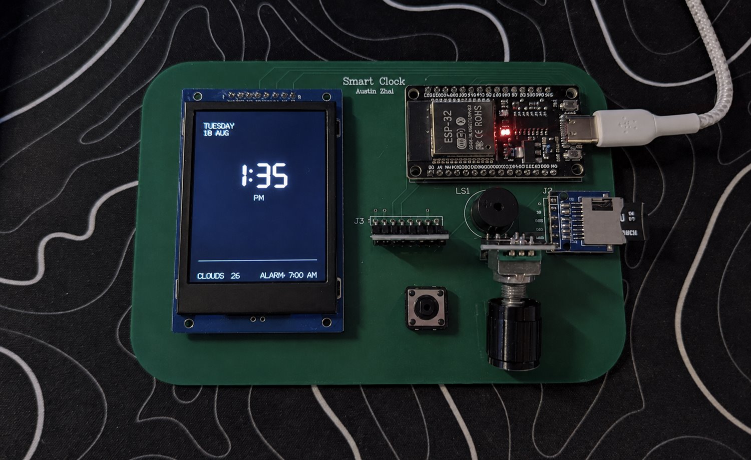
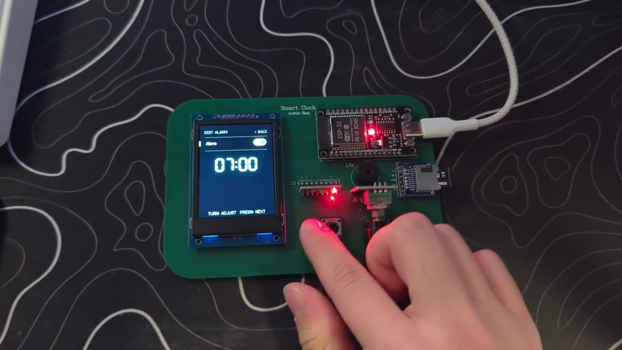
Ten screens, one knob, one button: the alarm, the smart alarm, your sleep data, the weather and the settings.
- Sets its own time from the internet and pulls a five-day forecast
- Redraws only the digits that changed, so the screen never flickers
- Alarm and snooze settings survive being unplugged, so the clock wakes up exactly as you left it
Part 2 · Sleep tracking and on-device ML
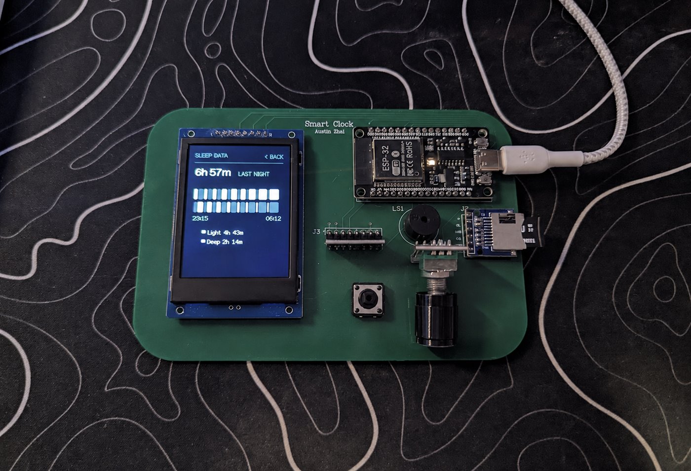
A motion sensor sits on the mattress next to the pillow and records how much you move, twice a second, onto a memory card.
- Every 30 seconds: half a minute of movement boiled down to 21 numbers, scored as light or deep sleep
- The verdict is saved as it goes, so the chart survives overnight even if the power drops
- Trained on eight nights I labelled by hand, roughly 420,000 readings
- Converted to run on the clock itself, no phone, no server
Below the baseline, and worth saying plainly: mattress movement alone barely separates light sleep from deep.
Part 3 · Schematic and PCB
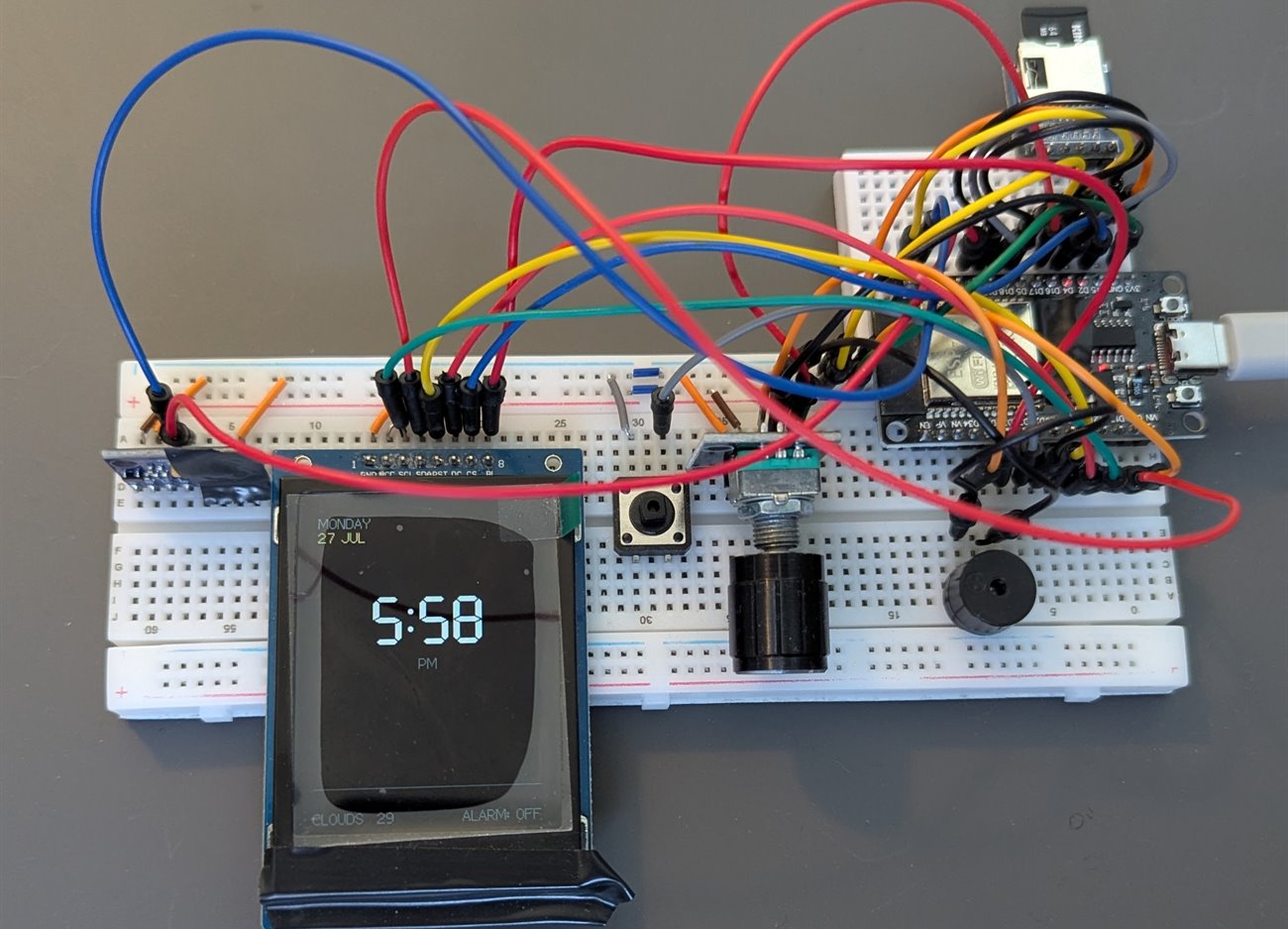
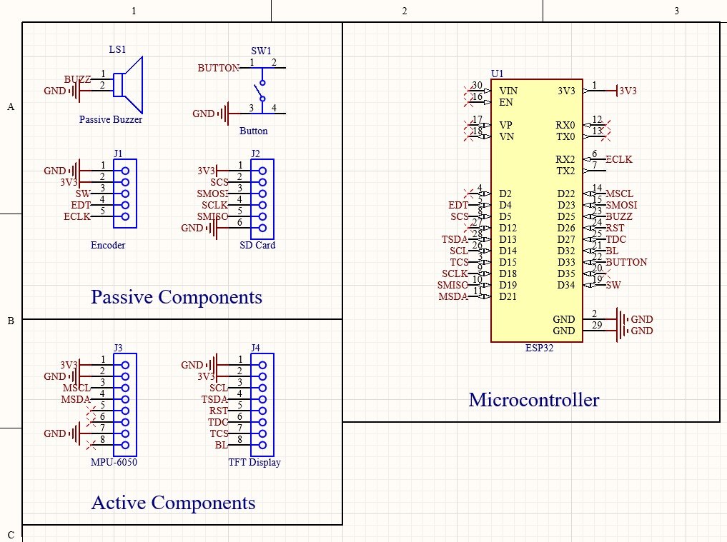
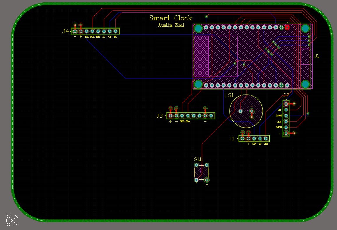
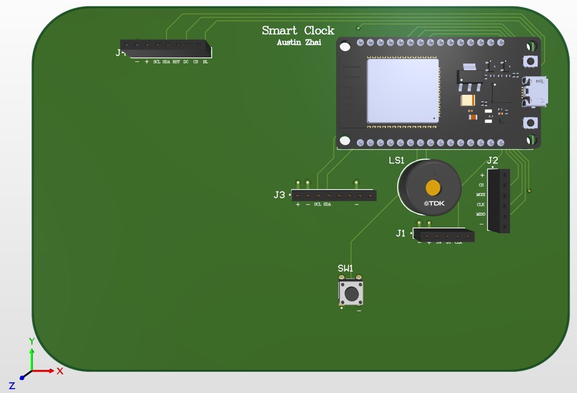
The first version lived on two breadboards with the display taped to the front. Once I stopped moving wires around, I redrew the whole thing as a real circuit board and had it manufactured.
- Every part breaks out to a labelled socket, so any one of them can still be swapped
- Same code, considerably less wire
Highlights
- Rings early at the first stretch of light sleep, at one of three sensitivity levels, and falls back to the exact alarm time if that moment never comes
- The model I trained ended up below a plain always-guess-light baseline, so I did not ship it as the displayed stage: see the numbers above
- Shipped the standard sleep-cycle model instead: 20 to 27% deep sleep, matching published norms, with my model’s guess still logged every window for comparison
- Roughly 1,100 lines of code plus a 1.4 MB model outgrew the chip’s default program space, which meant redrawing how its memory is divided up
- A button that double-registered and a pin needing a resistor the chip doesn’t supply, both caught on the breadboard and fixed in the board design
- The memory card file opens once per sleep session, not on every write. An earlier version corrupted the card doing that, so the rule is now built into the code
Projects · Software · 2026
Portfolio Vision
A web app that takes a portfolio of funds and shows you the companies you actually own underneath them, with live prices and a breakdown by sector and country.
Built first as a command-line tool, then rebuilt as a full web app running at portfoliovision.online.
Part 1 · Command-line tool
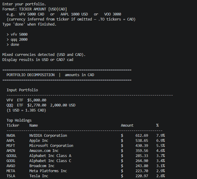
The first version ran in a terminal. You type in what you hold, and it opens each fund up into the companies inside it, repeating that on any fund it finds along the way.
- Prints the combined result with sector and country breakdowns
- An honest note on how much of the portfolio it could not account for
- Two funds holding each other would loop forever, so it watches for that and stops
Part 2 · Web App
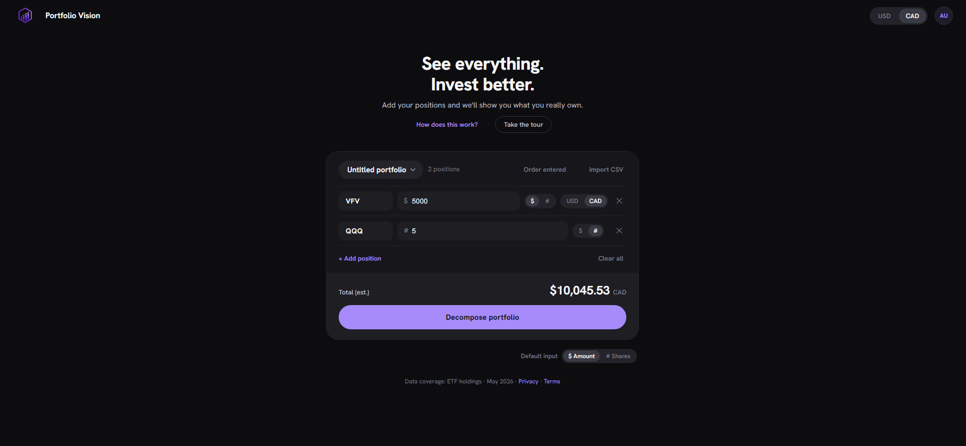
The web version does the same work behind a real interface, live at portfoliovision.online.
- Sign in with Google or a code emailed to you
- Portfolios save to your account, where nobody else can reach them
- Prices come in live, and the whole thing flips between US and Canadian dollars at the current rate
Highlights
- Opens funds up into what they actually hold across 750+ tickers, following funds inside funds without ever going round in circles
- Live prices across the US and Canadian exchanges, fetched through a small service I wrote rather than a paid data provider, which cut $30+ a month in costs and the request limits that came with them
- Sign in with Google or a one-time emailed code, with rules on the database itself so one account can never read another one’s portfolios
- Switch between US and Canadian dollars at the live rate, either for one holding or across the whole portfolio
- 400+ page views in the first week after launch
- Built, deployed and running on my own domain, with every key kept out of the code
Projects · Hardware · 2026
PocketSense
A pocket-sized room monitor on a circuit board I designed from scratch. Temperature, humidity, pressure, UV and WiFi signal on a small screen, paged through with three buttons and running off AA batteries.
Breadboard, then schematic, then board, then switching it on. I wrote the code, drew the circuit, laid out the board, and soldered every part by hand.
Part 1 · Breadboard and firmware
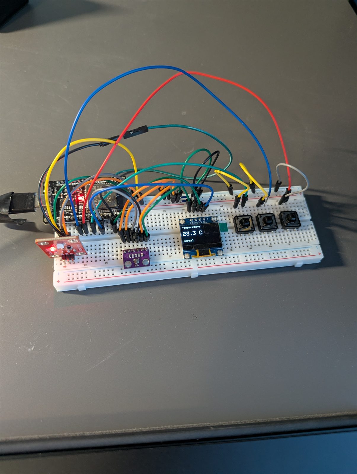
Nothing got committed to a board until it worked on a breadboard first: the whole program was written and proven before I drew a single line of the circuit.
- The sensor and the screen share one set of wires to the processor, a clash worth finding while it is still a jumper wire away from fixed
- The UV sensor sits on a pin that keeps working while the WiFi radio is on
- Deliberately small interface: five screens, three buttons
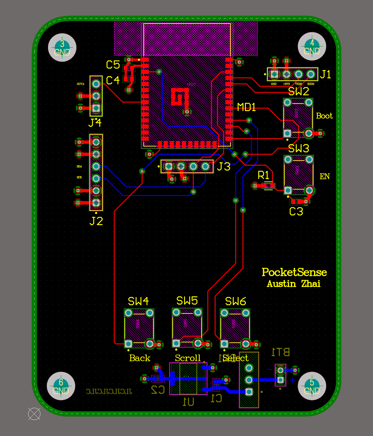
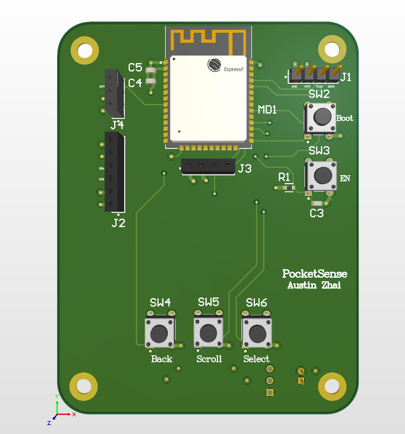
Part 2 · Schematic and PCB
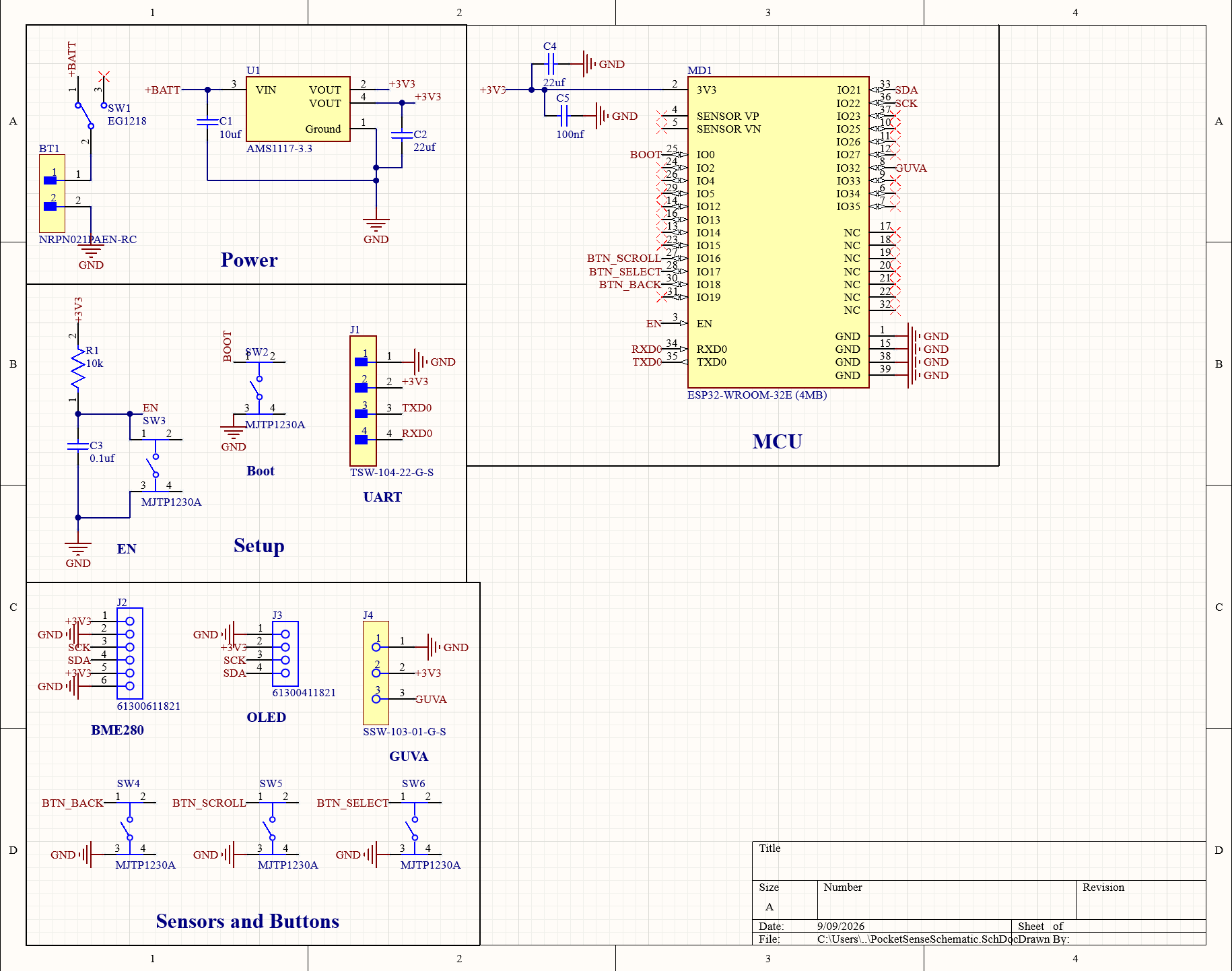
Drawn as four blocks: power, reset, startup, and the connector I program it through.
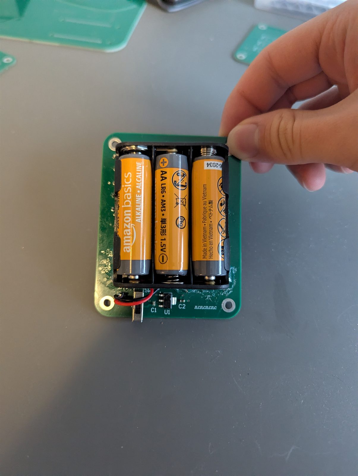
- Three AA cells feed a regulator through a switch that cuts the supply itself, so the board is genuinely dead when off
- Four layers, with solid power and ground through the middle and a deliberate gap left under the antenna
- Design checks came back clean, and I previewed the manufacturing files with the fab house before ordering
Part 3 · Assembly
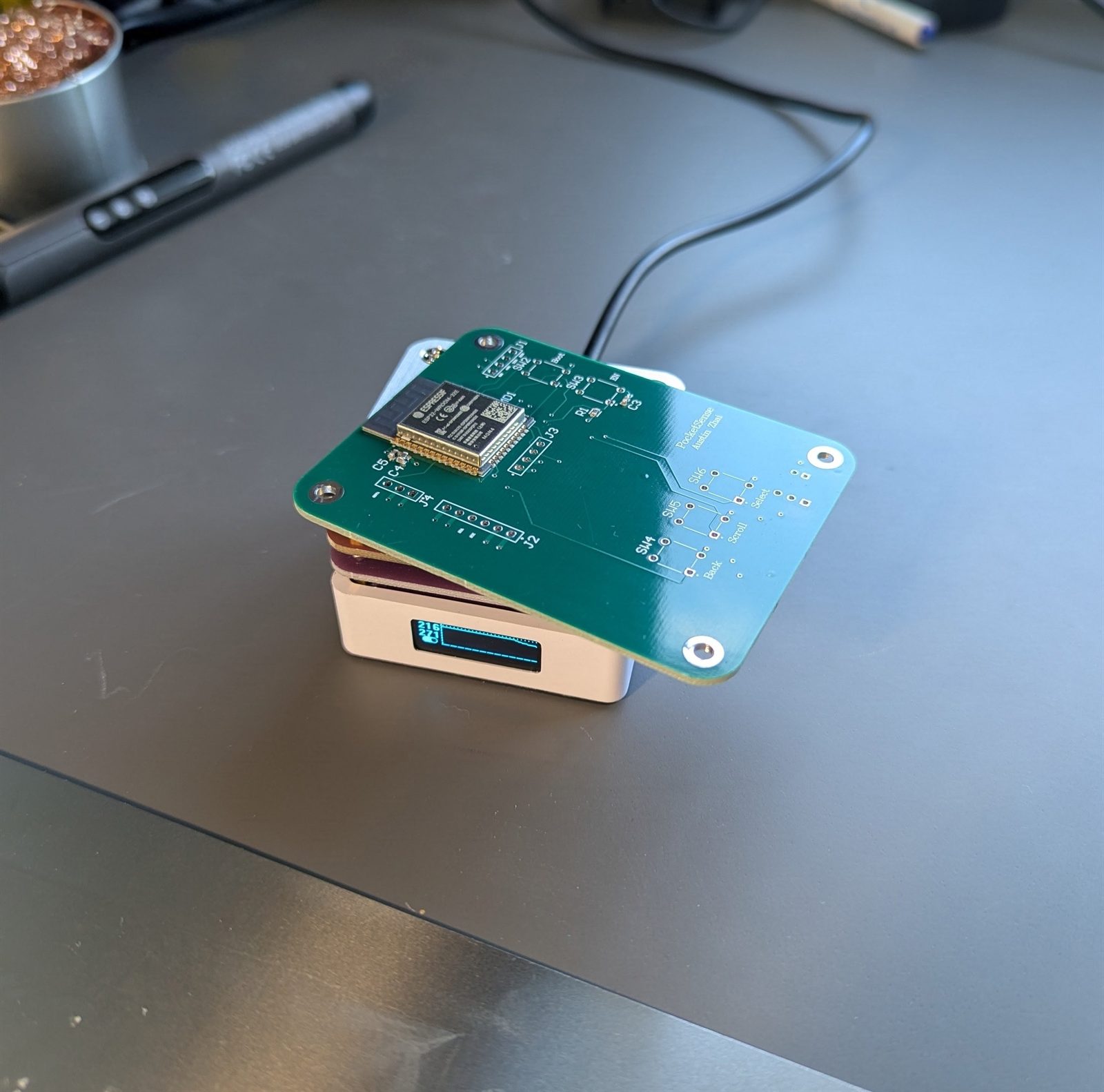
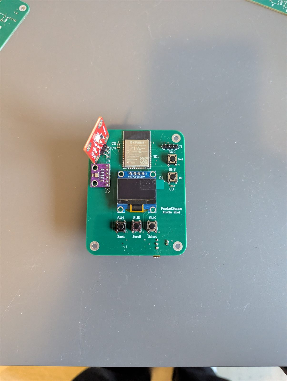
The boards came back from the fab house and I soldered every part by hand, flat parts first while nothing tall was in the way.
- The switch that arrived had more pins than the footprint I drew, so I traced it with a meter and found the three that line up, rather than reordering
- Checked power and ground for a short before any voltage went near the board. No beep, safe to switch on
Part 4 · UART bring-up
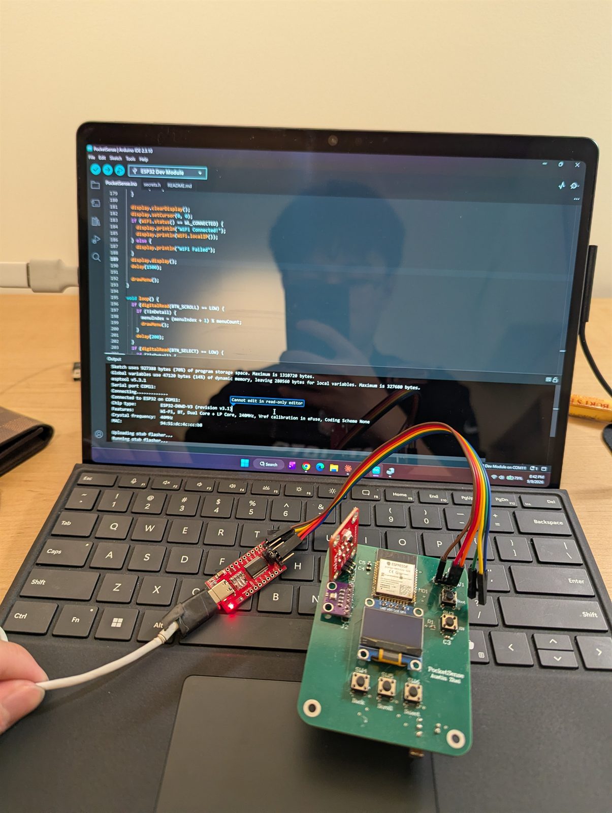
This board has no circuit to put itself into programming mode, so you do it by hand: hold one button, tap the other, let go, all within the second the computer is trying to connect.
- It works: the chip answers and the transfer starts, meaning the reset circuit, data lines and power supply are all doing their jobs
- Then the transfer dies partway, and the meter explains why: the supply sags under real current and the board cuts out mid-upload
- A battery and regulator problem, not a layout one
Highlights
- Five sensor screens on one small display, all driven by three buttons. No phone, no app, no cloud
- The bug that almost shipped: two buttons were wired to pins reserved for the chip’s own memory. Caught it against the datasheet before the board went out
- The antenna gap took a second pass: clearing the outer layers doesn’t clear the solid copper underneath, which has to be cut away separately
- The program runs about 927 KB, roughly 70% of the space set aside for it, a lot for something that draws five screens
- Every stage was mine end to end: code on a breadboard, circuit and layout, files to the fab house, every part soldered by hand
- One step from done: the upload cuts out when the batteries sag, and the fix is a steadier supply, not a new board
Projects · Software · 2026
Personal Website
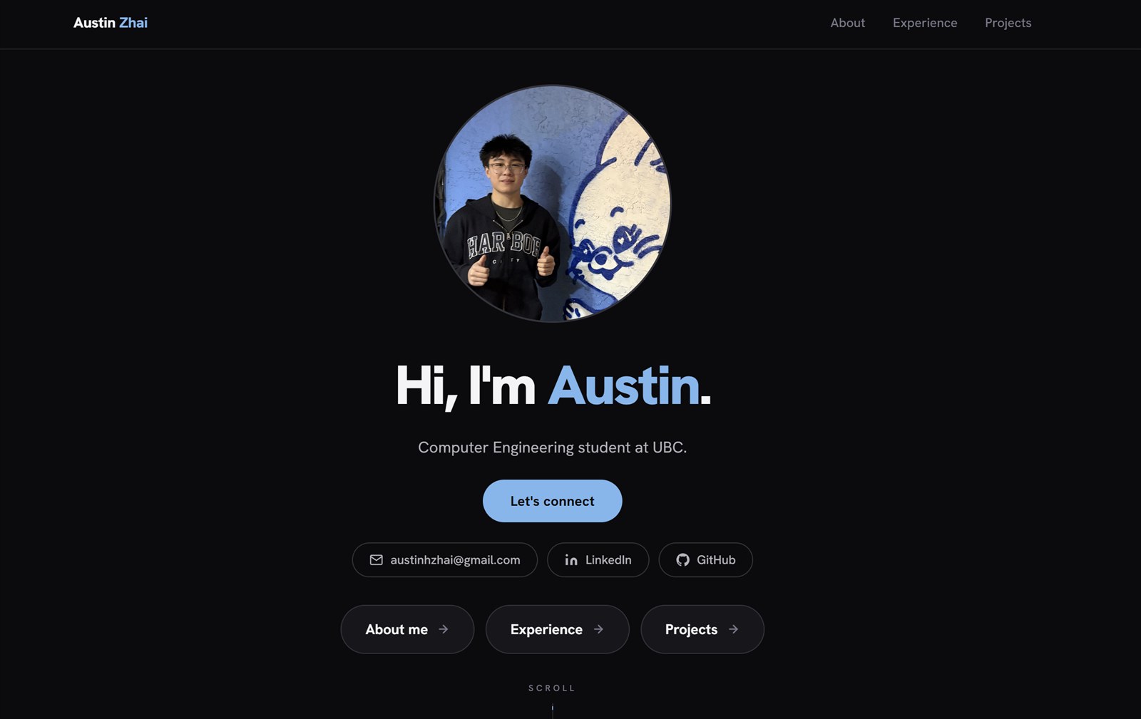
Designed, built, and deployed austinzhai.com end to end. A React single-page site with a dark theme, scroll-triggered reveals, and a projects page that prints as a clean resume.
Full CI/CD through GitHub and Vercel, with the domain and DNS set up from scratch.
Languages: JavaScript, HTML, CSS
Frameworks: React, Tailwind CSS, Vite
Tools: Git, GitHub, Vercel, Domain Setup
Highlights
- Mine end to end: design, build, deploy, and the domain it sits on
- Under 100 KB of JavaScript, and the page is up in under a second from a cold load
- The projects page prints as a clean resume-style document, laid out separately from the screen version
- Every push to the main branch deploys itself
Additional projects
Servo Sonar Radar · 2026
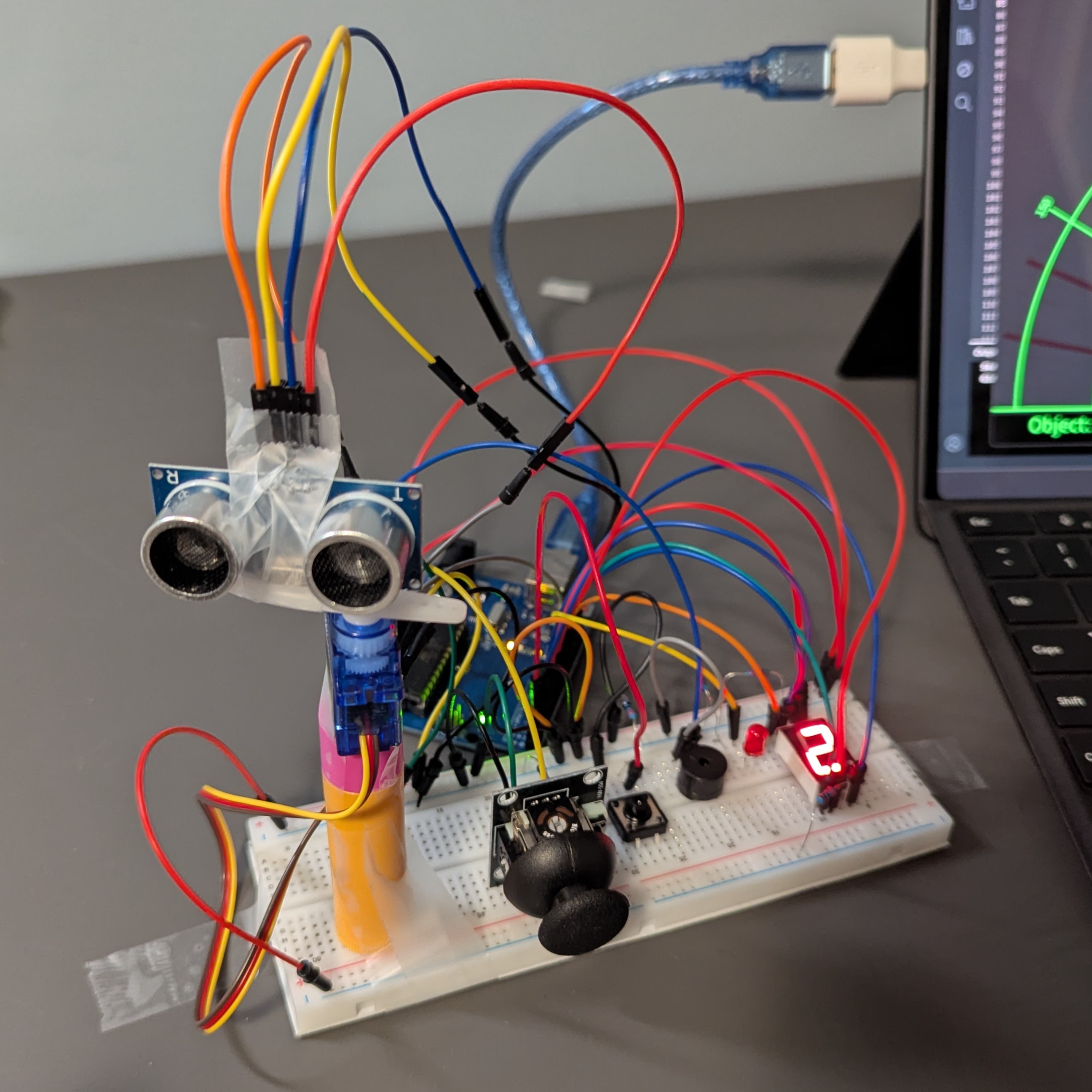
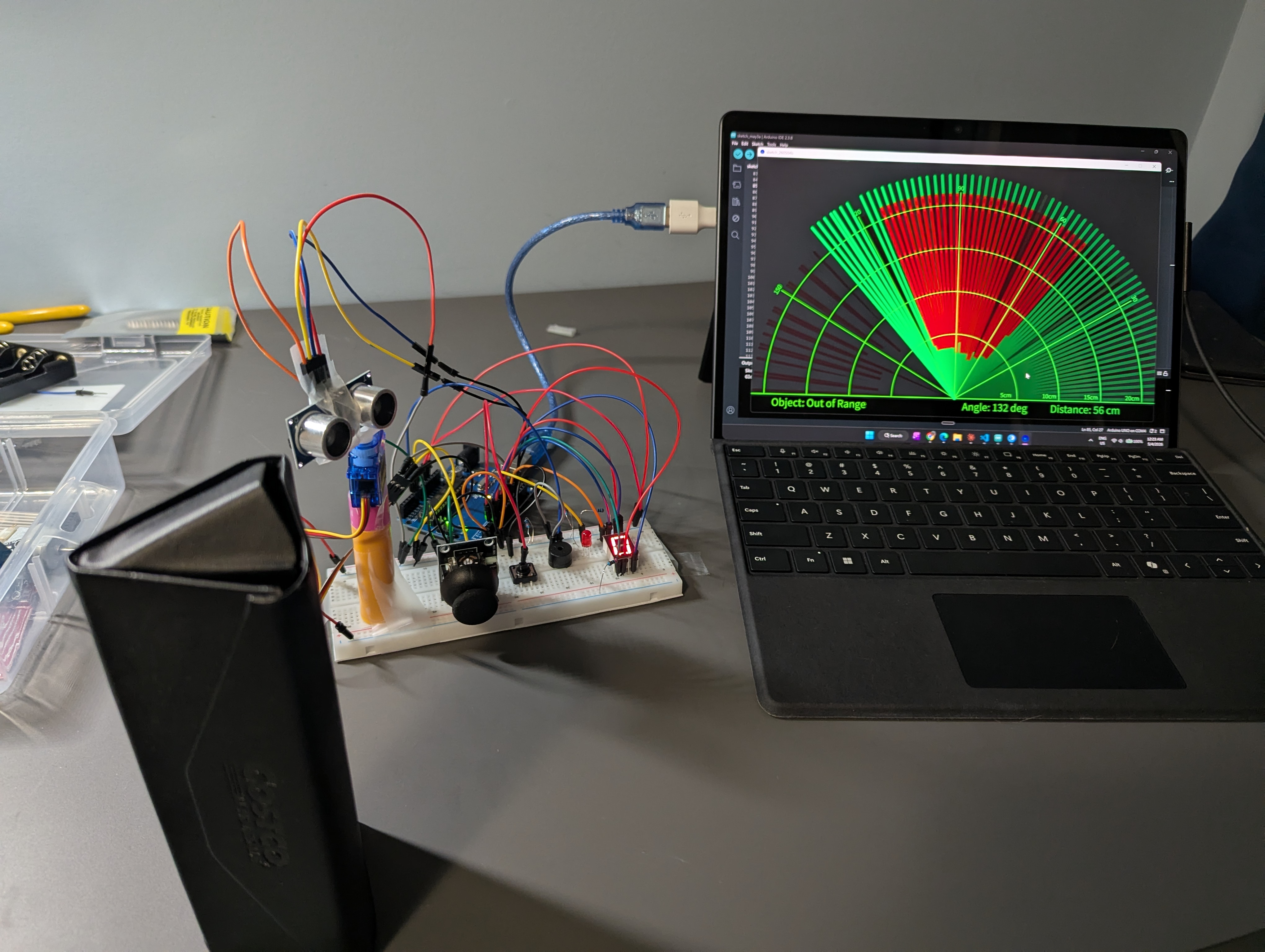
An ultrasonic sensor on a servo sweeps back and forth through 180°, measuring the distance to whatever is in front of it. Anything it finds is drawn on a live radar display on a laptop. Three modes: sweep continuously, stop when something is spotted, or aim it yourself with a joystick.
Smart Gate Access System · 2026
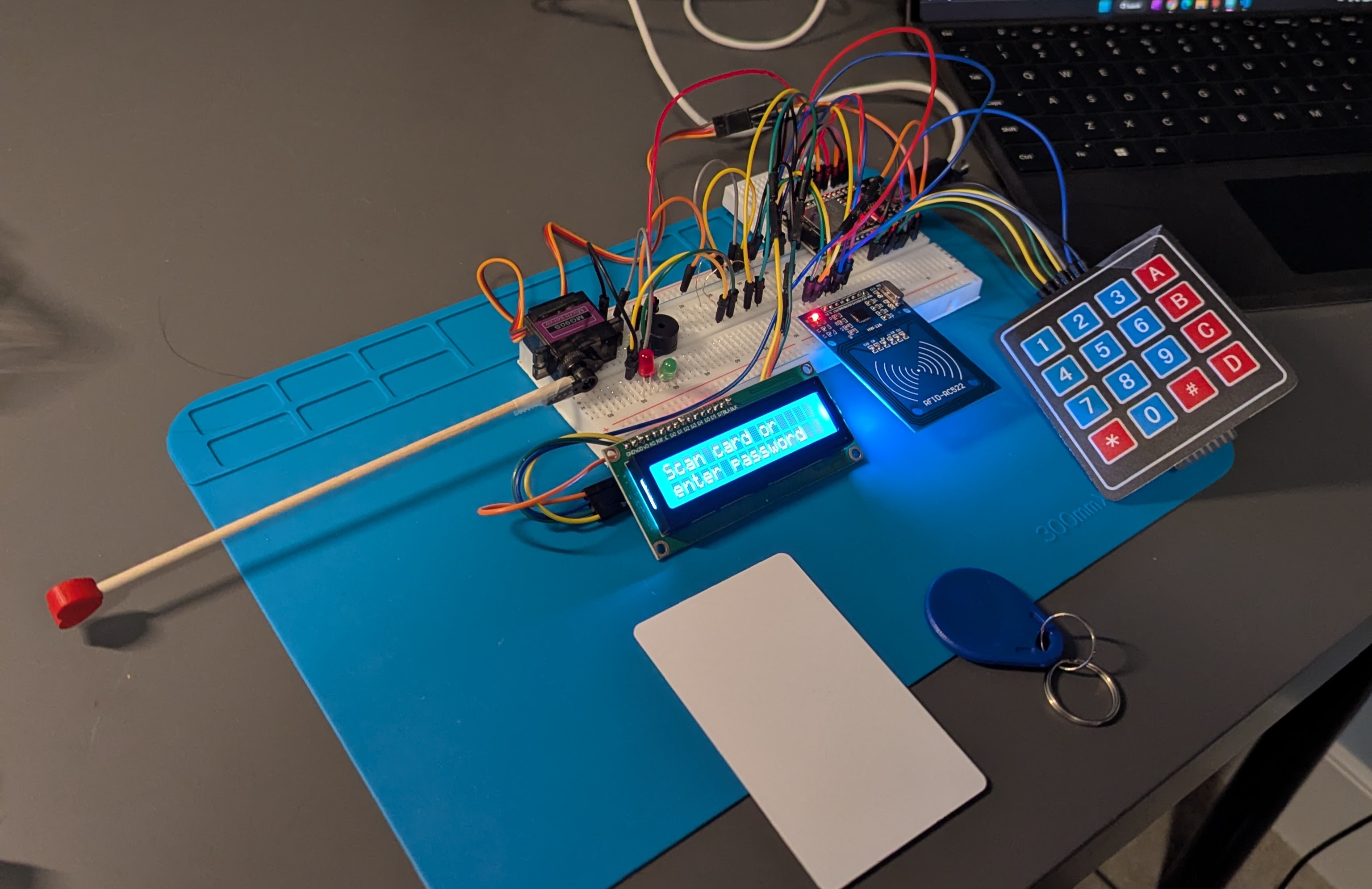
A gate that opens either to a tap of an RFID card or a code typed on a keypad, then swings shut behind you. A small screen shows what it is doing, and a light and a buzzer tell you whether you were let in or turned away.
Stock Predictor · 2026
A Random Forest classifier that predicts next-day S&P 500 direction (up or down) from historical price and volume data pulled via yfinance. Trained and backtested in a Jupyter notebook, reaching a precision score of about 0.58 on held-out data.
Hangman · 2026
A command-line implementation of the classic word-guessing game. Players choose a difficulty, then guess letters or the full word with 6 lives. Draws from a curated word list per difficulty and tracks guessed letters to prevent duplicates.
Random Password Manager · 2026
A command-line Python password manager that stores, retrieves, and deletes credentials locally. A built-in generator guarantees variety across uppercase, lowercase, digits, and symbols on every run. Data persists via a local JSON file.